https://ip.sandia.gov/technology.do/techID=175
Do you think this is real?
Author: crackingcontraptions_3voi0v


The code should not be run in debugger mode.
|
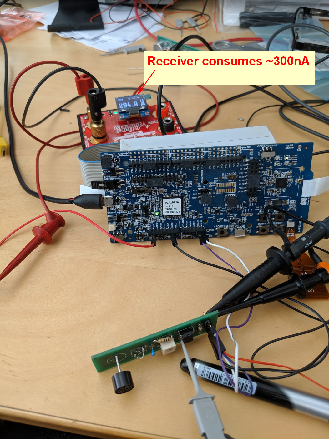
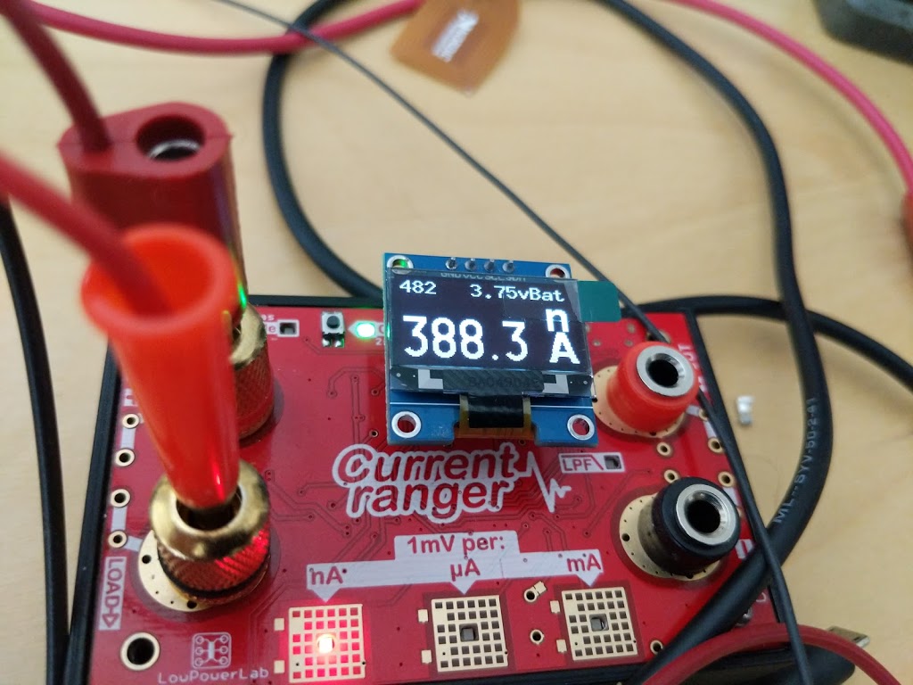
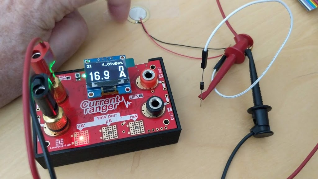
| YAY! ~400nA |
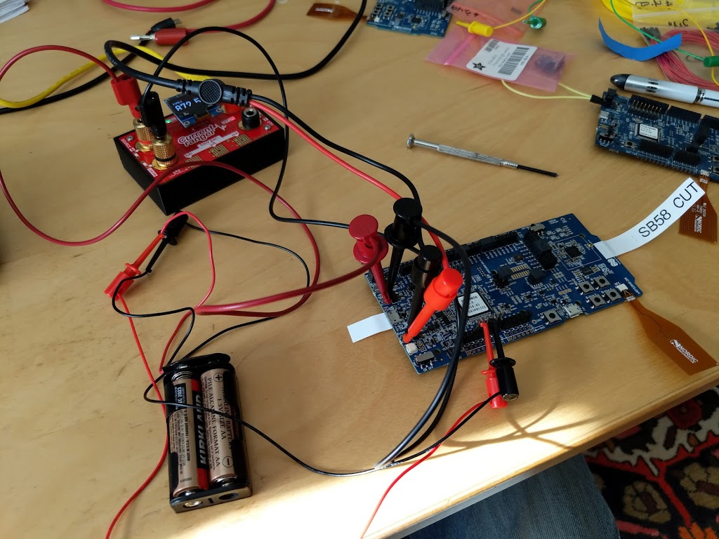
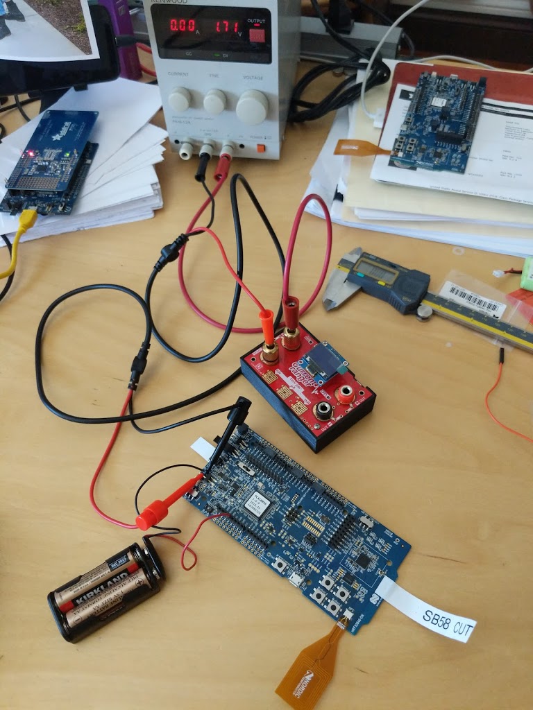
The setup was too complicated.
I connected the bench PSU to P21 and supplied 1v8.
 |
| Connections |
 |
| Switches |
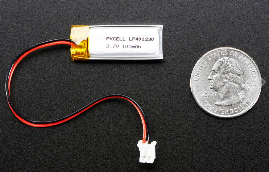
I don’t see a point in using a super-cap for energy harvesting apps. May as well use a lipo, which has better power density.
For battery charging purposes maximum power-point tracking seems to be a good thing.
Looking at the energy harvesting regulators that David found they seem to be specialized for different applications:
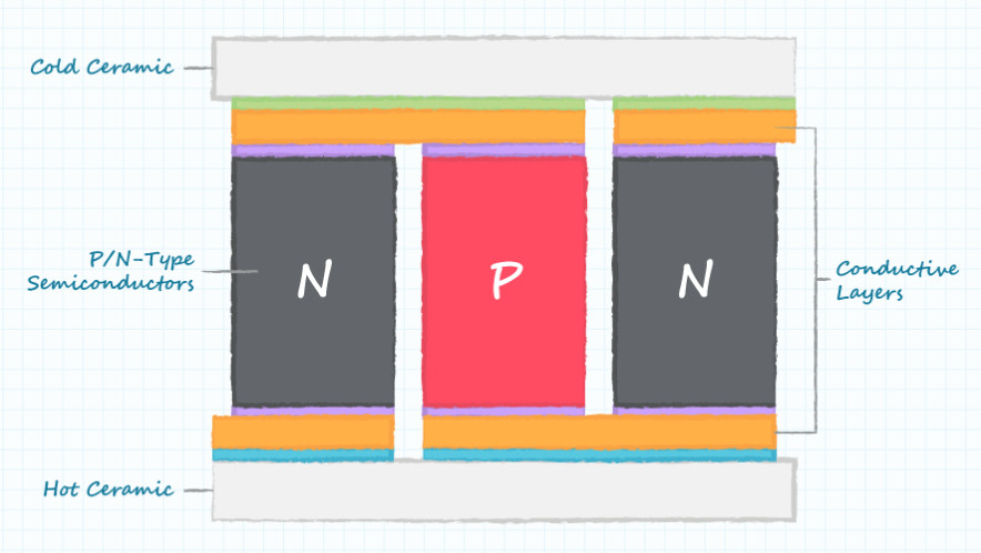

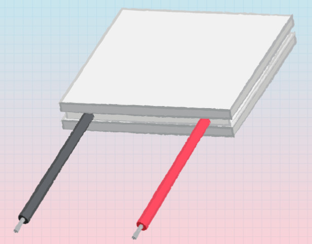
Using it backwards to generate electricity is called the Seebeck Effect. From the examples on this video it looks like you need fire on one side, and ice on the other to generate enough current to charge a phone!
Here’s a 12V Peltier plate spec
Model: TEC1-12706.
Size: 40mm x 40mm x 3.6mm.
Working current: 4.3-4.6 A (rated 12 v); Imax: 6A.
Rated voltage: DC12V (Vmax: 15 v starting current 5.8 A).
Operates Temperature: -30℃ to 70℃.
Refrigeration power: Qcmax 50-60 w.
They come in sizes as small as 15x15mm from Digikey.
Have to get good contact between the heat source/sink and the Peltier. Here’s some heat conducting glue. Also probably need a heat-sink.

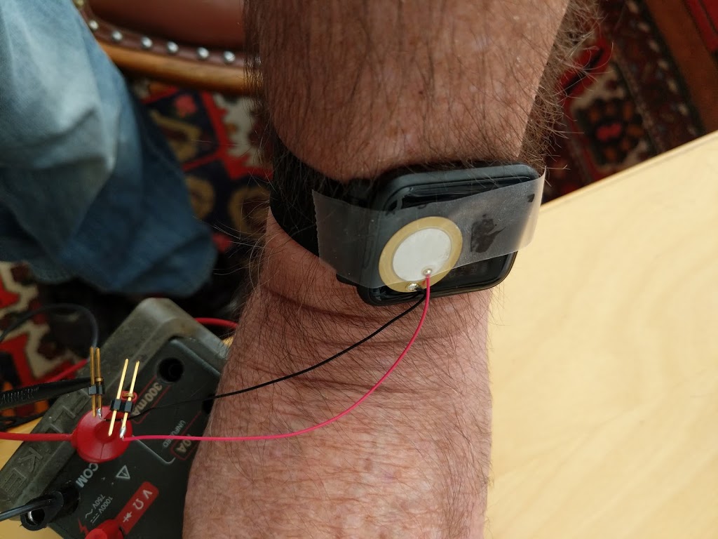
Here is a proof-of-concept Peltier watch which at least shows it’s feasible.
Latest update is not great news. I wonder how often you have to get your wrist out in the sun to be effective.
Cool Video – https://www.indiegogo.com/projects/smartwatch-powered-by-you-matrix-powerwatch-2#/
I wonder where the solar panel is?
LTC3106
LTC3107
LTC3108-1
LTC3108
LTC3109
ADP5091
 |
|
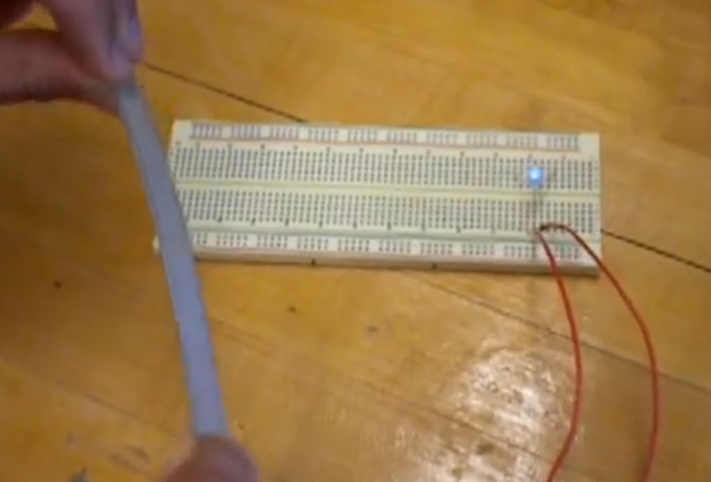
LED illuminates momentarily each time the piezo strip is flexed
|
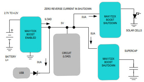
Here is an app schematic that seems to handle both solar and capacitor.
And here is one designed just to charge a cap.
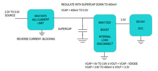
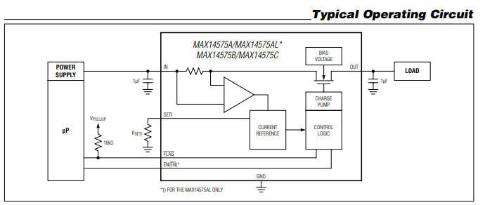
But the MAX14575 requires that the input voltage is the same as the desired output voltage. Also it seems to have some limit on the size of capacitor it can handle.
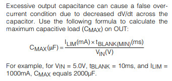
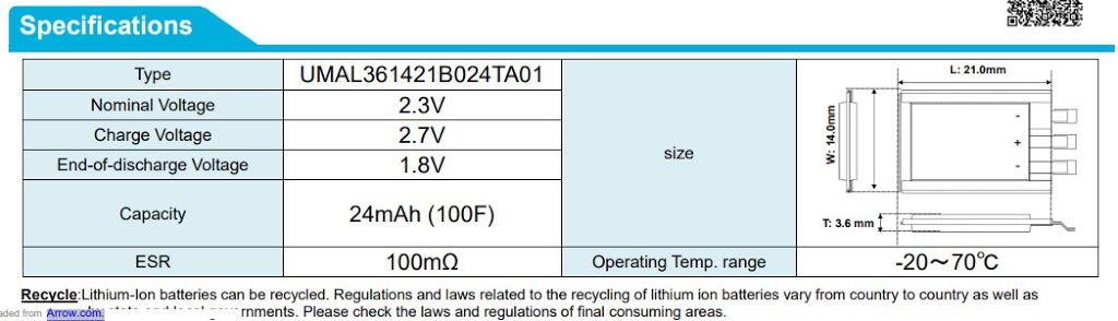
For a 100F SuperCap 100,000,000 = (250 * tBlank) / 2.7.
tBlank = 1080 seconds!
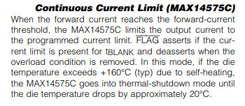
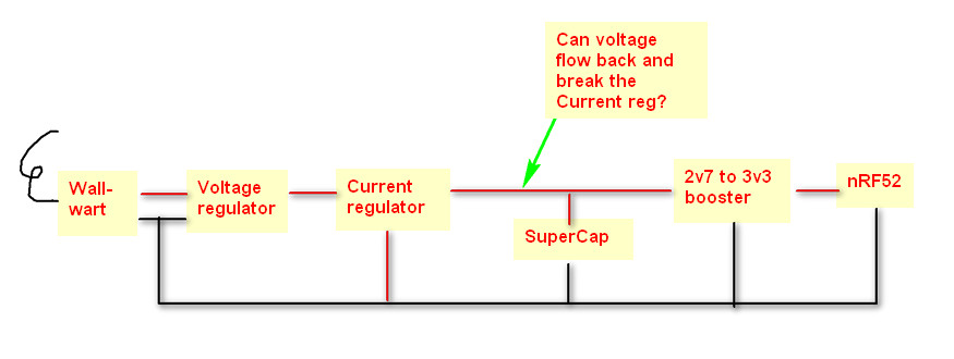
So it seems like it will turn the output on/off until the overcurrent condition goes away. The duty cycle will be about 3%. The alternative is to use the 14575C which does not duty cycle, but it might get hot!
The MAX667 seems to limit the voltage and the current (to 250 rather than 240, but hey). But perhaps it doesn’t limit the current drawn, and simply get’s hot and angry.
I found two ICs that might be able to limit voltage and current. There are probably others.
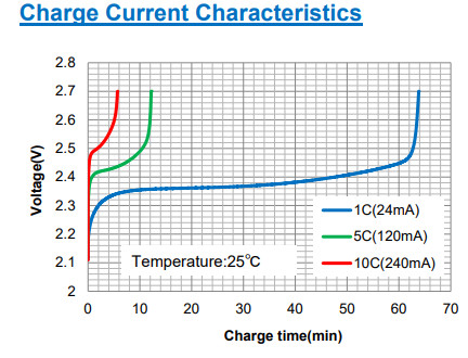
I need to see if they can limit voltage to 2v7 and current to 240mA.
TLV70227QDBVRQ1 looks like this.
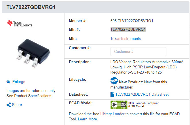
So basically, I’ll have the LDO sucking 5v5 and blowing 2v7 at 300mA into the current limiter which will pass through 2v7, but chop the current at 240mA (10C).
Now my question is, do I really need the current limiter, or can I rely on the LDO to limit the current, or does it catch fire if the supercap tries to draw too much?
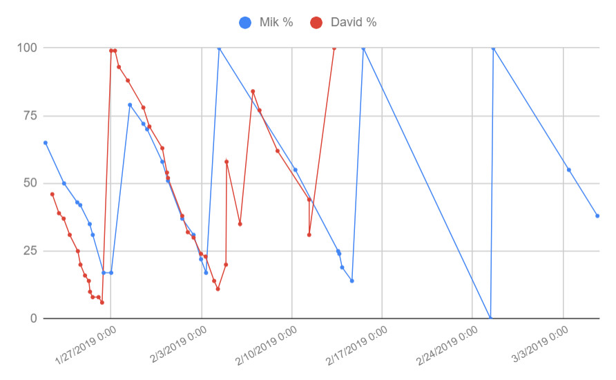
The Amazon BiP sports a 190 mAh battery. Our data shows that it can listen for BLE packets for at least 10 days. It’s also running sensors, a display, and a GPS periodically.
I’d like to make a PSU that can try out a whole bunch of charging strategies:
Instant = seconds to minutes.