It was a much better fit. It’s still probably tight enough. I slipped it on my wrist and have been wearing it almost continuously for since I got home, about an hour ago.
It’s actually easy to put on quickly.
The Bad
The molding had rough edges from where I removed the top hat – always to be expected. I filed it down.
The end of the cuff by the opening digs into my arm still. When I removed it there were indentations on my wrist, which is probably going to be unavoidable to get a snug fit. More worryingly, red marks were beginning to develop on my wrist.
The Ugly
It isn’t that it’s too tight, it’s more that it is a poor fit. My mistake is assuming that the wrist is symmetrical. Notice that it doesn’t wrap around and meet symmetrically on the middle of the underside of my wrist.
One of the more irritating things about my washing machine in my house here (and the dryer) is that I don’t hear them finish. Perhaps I do, but I ignore it. I have seen all sorts of home-brew devices for monitoring the LED on the front and generating an IFTTT message when the light turns off. The latter can then send a message to your phone, or whatever. The problem is that my washing machine doesn’t turn off its’ LED, and my dryer doesn’t even have an LED. The other thing about these devices is that they require a PSU, and have to be stuck on the front of the appliance.
I just thought it would be cool to have some device that a consumer can simply clip over the cord to their appliance, and whenever there is enough power, it boots up a processor, and sends out an IFTTT message “appliance X started”. When the power subsides, the processor uses it’s accumulated power to send a an matching “Appliance X stopped” message. When combined with an IMU to detect vibration, a clock to measure delays, and a microphone to measure noise I think one could cover a whole range of washing machines, and dryers.
I’m looking for a low-power way to wake up the processor from deep sleep. I have experimented using the Invensense IMU, but it is not very responsive., when it is operating at its lowest rate (0.25Hz). It sometimes requiring several heavy taps to generate an interrupt to the processor, and it draws 8uA. At a more responsive rate of say 8Hz it works ok but drawers 10uA. On a CR2025 at 225mAh it could stay on standby for 2.5 years assuming it did nothing else at all. Atop that there is the processor load of about 100nA which is negligible really.
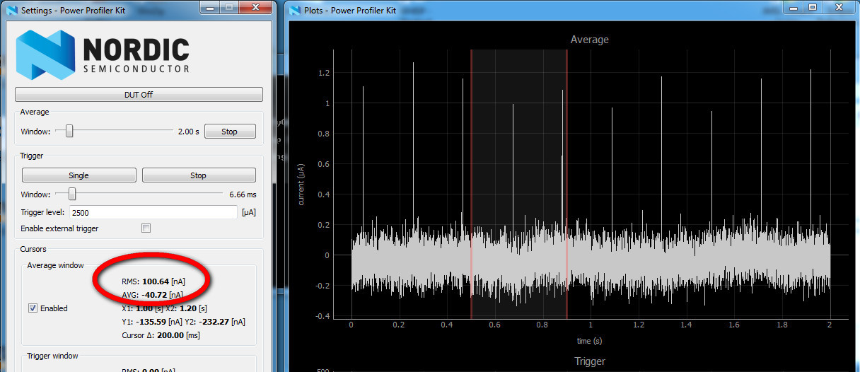
Here is proof (if only to my failing memory) that the off current really is 100nA.
I was thinking that it might be possible to just use a sensitive movement switch, and cut the sleep current all the way down to 100nA from the processor. I bought a few of different kinds from China, and have been trying them out. The best seems to be a rather large vibration switch.
Vibration Switch Tests
I connected all the switches via a 1M ohm resistor to a 3V supply for these tests
Notice that the sensitivity is detrmined by the orientation, much as you would expect. Just checkin’.
GAOXIN SW18010P (Normally ON)
There are several different switches in this class. The last two digitis in the part number seems to indicate the amount of effort required to operate them. The SW18020 takes more energy, so this one (SW18010P) is the most sensitive they make.
DonGrong 520D (Normally OFF)
It is a lot more sensitive, though I need to test it in a bunch of different orientations.
GikFun HDX-2 (Normally OFF)
Using it to wake up the processor.
The SDK can be configured to wake up from deep sleep in response to a button press. In deep sleep it consumes 100nA if I get everything turned off. I figured the vibration switch could do the same thing as a button. SDK buttons are configured to pull a GPIO down to GND when pressed. The GPIO is configured with a pullup of course.
The vibration switch is normally (kinda) closed, and goes open-circuit when moved. So I can either have the switch pull a high GPIO low, or a low GPIO high.
Pull high GPIO low
I connected the switch between GPIO and ground, with a pullup on the GPIO. So when it is quiescent (closed), it pulls the GPIO low, but when the switch is disturbed the pullup on the GPIO drags the GPIO high, and the processor is triggered to wake up on pin-hi. This works OK most of the time, but not perfectly.
In quiescent state the switch is closed, and the processor is sucking about 800nA, which is about 700nA more than I expected. The problem is that there is some current leaking to ground through the GPIO most of the time.So perhaps I need a resistor of some sort to limit the current… or a capacitor? Need to do some high-school physics, or ask David.
Pulldown
In the other mode, the switch is connected between Vdd and the GPIO, and the GPIO has a pullup on it. Here’s the config line of code for pin #3.
In this mode it draws a 100nA when quiescent, which seems like a distinct improvement.
Demo
The following video shows how easily (and sometime not) it wakes up. When the 4 LEDs are off, the processor is asleep, consuming 100nA, By the time the LEDs come on, the processor has reset, and rebooted from scratch, and it sets up the vibration switch to interrupt, and goes back to deep sleep.
This seems pretty promising. The switch triggers the processor on quite small movements, and in all the orientations I tried.
<Old video removed – see the one below>
So at 100nA on a CR2025 it could last 2250000 hours = 256 years. Yeah… right!
Issue
The main issue as can be observed in the latest video is that the switch occasionally sticks ON, and it takes a bit of a tap to free it. This is no good of course. Could it be just a mechanical issue, or is it welding itself closed? Perhaps the quick slew of interrupts is overwhelming it in some way, and I need to slow them down.
Orientation
Now I’m going to see if the two NO switches work in all orientations.
DonGrong 520D (Normally OFF)
There seems to be an issue with orientation. The DonGrong is pretty unhappy in four out of six of the major gravity orientations.
GikFun HDX-2 (Normally OFF)
This one seems a tad better in that it seems to get stuck in only two orientations.
Interim Conclusion
Orientation is an issue for all mechanical switches.
But clearly with 8 mercury switches mounted at appropriate angles, in series with the vibration switch, the latter could be disabled at the critical angles where it doesn’t work well. I lashed up something to see if I could disable the vibration switch in one of it’s difficult quadrants, and I could! I really needed two sets of four pointing up at 45 degrees, and another set pointing down at 45 degrees in series.
But even if this worked, I would need two vibration switches, each with it’s own constellation of 8 mercury switches. if this is going to work for every angle, and only use a single GPIO pin. (I think 12 mercury switches would do it, because they could share four. But that’s not going to be either pretty, or small.
BUT… another brainwave. I think it might be possible to do what I want with just two orthogonal tremblers connected to two seperate GPIOs. But I’d have to figure out which one is best to generate the processor interrupt before I send the processor to sleep. So reading the accelerometer would provide the gravity orientation, and then before shutdown I could select the best trembler.
AND… of course it is important to be able to turn the IMU fully off, so that it consumes zero power. That’s going to require another GPIO, or a programmable latch of some sort, so now I am looking at perhaps three GPIOs to shut this puppy down. A GPIO can source 3mA (15mA total). The IMU needs 0.8mA max, so maybe it can be powered directly of the GPIO. This link explains the limits well.
We recommend 15mA total current sink/source on the chip for normal operation. This can be on one pin if you want (different than nRF51). We recommend that you sink current rather than source current because of more ground pads than vdd pads.
So I hacked a bit more and here’s a new prototype.
What I need to figure out now, is how to have the processor sleep until all the physical activity ceases, and then wake up again, so it can activate the tremblers and go into full sleep mode. The question is how little power does the accel. need in order to notice settling. And then is it possible to tell if the processor has woken from a trembler wake-up signal, or an accelerometer go to sleep signal. I might have to leave one bit of persistent memory to do that!
I think I may have discovered that it isn’t possible to wait for significant motion to stop.
Persistent RAM
This was a struggle. I managed to figure out how to store data in RAM across a SYSTEMOFF sequence. The challenge is figuring out how not to leave more memory than I need switched on.
There is actually an 8 bit register that I discovered persists across SYSTEMOFF. Since I only need one bit, well perhaps two, I could have saved myself a chunk of sweating.
Discussion
David:
I read most of your post two days ago when you posted it but hadn’t finished so didn’t comment. I can’t tell much from the video except to see that when the board was tapped there was a response in the scope. That switch is quite interesting. I’m intrigued with how it works, especially since it is normally closed and isn’t “snap action”. Maybe it has some type of wax in it. Did it come with a data sheet?
How big of a pullup or pulldown resistor can you have? I think you saw 700nA because of burning power through the pullup. Current will flow as long as the switch is closed. In the other configuration, current also flows through the pulldown until the switch opens, so I don’t understand why the current measured was less (100nA). The resistor needs to be as large as possible to get down to nA current values. A 1M resistor will draw 1.8uA at 1.8V.
What you thought up is really cool. Now if there is a smaller version of the switch available. Can you send me the link to it?
Mik:
I was trying to get a clean bit of video to post, which is why I never finished.
The problem is that every now and again the lights get stuck on – usually after a heavy tap. It’s like the switch get’s physically jammed. One problem is that the switch is probably generating a whole bunch of of interrupts in quick succession. I thought that if I put some capacitor, or some random diode in series, or in parallel (you can tell how scientific I am being) maybe I could make it smooth them all out somehow.
Sensitivity: Actually as I type this message each keystroke is triggering the LEDS on/off – and it’s a good foot away from my keyboard.
Flashing: it seems like each tap is triggering multiple interrupts. I can write code to debounce the switch, but it seems to keep ringing for several seconds sometimes.
It sticks on if I hit it a bit too hard.
Data sheet? The switch I’m using dimply came in packet marked Gikfun HDX-2 Vibration (“Geek Fun?”) I’m just using the programmable internal pullup provided by the Nordic uC. I have the current down to around 100nA now, and that seems to be about as good as it can get with the button-press demo program they provide. I find the Nordic documentation a bit confusing, so maybe it can be lower, bit I don’t see how.
I am so far out of my depth, so please suggest ideas.
I can’t see why it would get stuck if there is only a very small current.
Thinking some more, a normally-closed spring-type vibration sensor (like the picture) is probably going to be less reliable than a normally-open type, and it’s more difficult to use. A pullup on a GPIO with an open switch to GND isn’t going to draw any current. What do think about ordering some of the NO sensors?
Mik:
I didn’t show you my other tests. I did all four again today – a little more carefully so I could get your comments. I updated http://blog.touchstone-labs.com/2017/04/vibration-switch.html Re. your links: The three NO switches you pointed me at are (I think) the same as what I have. (My previous test was with an NO switch, I was confused) I don’t have a tilt sensor. It would be good to try and see if it had any advantages, but it seems like it would have the same issues as the mercury switches, and get stuck on in 50% of the orientations. I checked out all the modules (at Ali Express) but they all needed power, which was what I was trying to avoid. Perhaps they are more reliable though.?
Mik:
Recall I said that the vibration switches I was experimenting with, seem to get stuck at certain orientations? I found these tiny switches , but they are NC switches. I want NO so as not to consume power. I wrote to the support person to ask if they had NO versions.
Hi Mik,Thanks for your questions. Yes, these sensors are normally closed, or on, so to speak. We do make some normally open, or off, devices though these are relatively high g level shock and acceleration switches.High sensitivity mechanical parts will self trigger if normally open because gravity will cause the devices to close. Best,Mark*********************************************Mark Nathemnathe@signalquest.comwww.signalquest.com
They actually need 5G to trigger which is way too much. As he mentions, there is a constant 1G vector acting on any switch of course, and I need a switch that triggers when there is a small change in the gravity vector. So it seems like my solution, which uses two switches at right angles, is the way to go. The trick is to make sure that the correct switch is selected based on the orientation. You’d think they would have an integrated product for that wouldn’t you?
I found some wakeup radio activity. Some of the recent stuff looks almost usable, but of course I don’t understand the electronics, so it might all be bogus..
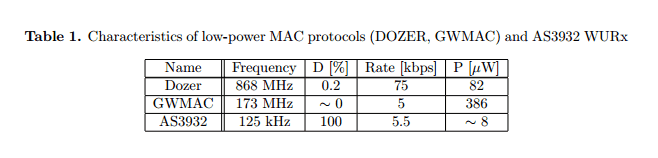
One of the very few commercially available is a low-power, low-frequency wake-up receiver chip with addressing capability AS3932 [14]. Gamm et al. [15] designed a low-power WURx circuitry around it. The main transceiver produces a 125 kHz wake-up signal OOK (On Off Keying) modulated on an 868 MHz carrier. They report communication range of 45 m when transmitting with main high-consuming transceiver with +11 dBm and over 15 m when using 0 dBm output power.
6. Conclusions and Future WorkWake-up Radio (WuR) systems provide significant energy savings for wireless sensors when compared to conventional duty-cycling approaches. In this paper, we investigated and characterized a promising novel WuR approach that is based on SubCarrier Modulation (SCM), which enables two radio operation modes. When the remote sensor node is in low-power wake-up mode, a Wake-up Call (WuC) can trigger it remotely. Afterwards, the node switches to data communication mode to start the data exchange, e.g., wirelessly reply a transducer measure back. In this paper, we analyzed the performance results of the SCM-WuR approach and compared them to state-of-the-art WuR systems as of 2013. We conveyed the detailed performance analysis of the SCM-WuR approach in terms of wake-up delay, current consumption and overall operational range. Through physical tests, measurements and simulations, we have shown that SCM-WuR systems feature an outstanding tradeoff between hardware complexity, current consumption and operational range. We also demonstrated how SCM-WuR systems enable multi-hop wake-up for even longer remote sensor measure collection. For this purpose, we implemented a wake-up relay node and characterized its operation through delay and current consumption analysis. Finally, we have presented two real sensor monitoring application cases with SCM-WuR system, one single-hop and one multi-hop scenario, and calculated the lifetime and packet delivery ratio of the latter through simulations. Indeed, SCM-WuR systems effectively enable a vast range of applications, while most state-of-the-art proposals are restricted to short and medium-range scenarios. To the best of authors’ knowledge, this study is the first one to perform such type of global analysis in the field of Wake-up Radio systems. As future work, we target the evaluation of SCM-WuR design for different frequency bands, a feature that allows its integration into different wireless technologies.
I wondered if we could sacrifice one battery for more board space, or if a flat rechargable LiPo would fit under/over a full width board. Just pondering.


